
Xilinx XADC Part 1 : Analog input
- Mar 13, 2018
- 2 min read
Introduction
The XADC is available on the Xilinx 7 series FPGA's, it includes a12-bit, 1 Mega sample per second (MSPS) ADC and on-chipsensors. The dual ADCs support a range of operating modes, for example, externally triggered and simultaneous sampling on both ADCs

The ADC supports different analog input types such as unipolar and bipolar analog inputs, also it provides up to 17 analog inputs which can be accessed.
The result of analog conversion for both analog channels and sensors are stored in status registers. The ADCs always produce a 16-bit conversion result. The 12-bit data correspond to the 12MSBs (most significant) in the 16-bit status registers, these status registers can be accessed by your FPGA design to acquire the sensor readings or conversion of the. as shown on the block diagram the status registers can be accessed also using JTAG, even if the XADC is not instantiated in the design you can still access it using JTAG and read the values of the temperature sensor and the supply voltage sensors.
XADC operating modes
The XADC can operate in the following modes:
Single Channel Mode
Automatic Channel Sequencer
Sequencer Modes
External Multiplexer Mode
In this tutorial we are going to discuss using XADC to sample analog signal using single channel mode.
External analog signal
Before start interfacing analog signal to the Xilinx FPGA we must first take into consideration the following:
for uni-polar inputs the amplitude range is 0 to 1V and Vn can have an offset up to 0.5V

for bipolar the differential analog input voltage range(Vp-Vn) is +/-0.5V and the common mode or reference voltage should not exceed 0.5V. To accommodate these types of signals, the analog input must be configured to bipolar mode. Bipolar mode is selected by writing to configuration register 0(by setting bit 10 in the register to 1).

Design details
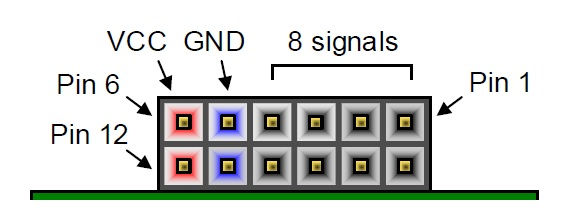
In this project the Basys 3 board will be used to acquire analog signal using the XADC in single channel mode, the Basys 3 XADC analog inputs can be accessed using XDAC PMOD connector, which gives access to channel 6, channel 7, channel 14 and channel 15.
1- In the Vivado block design add XADC IP
2- double click on the XADC IP and configure the interface options to DRP and the start up channel selection to single channel as shown in the figure

3- in the Alarms tab you can uncheck all as there is no Alarm used in this project

4- go to Single Channel tab and select VAUXP6 VAUXN6

5- connect the daddr_in port to switches by making it external and connect eoc_out to den_in.
6- use slice to extract the 12 most significant bits of the output and connect it to the ila as data and connect the eoc_out to the ila as trigger.
7- connect dwe_en and di_in to constant 0, the final block diagram is shown in the following figure

The switches can be used to read the internal status registers of the XADC however for the analog inputs, only channel 6 can be read, this is done by setting the switches to 0010110
To test the project Spartan 3AN board is used loaded with the 3 phase generator project, the generated analog sinewave is connected to Basys 3 XDAC PMOD
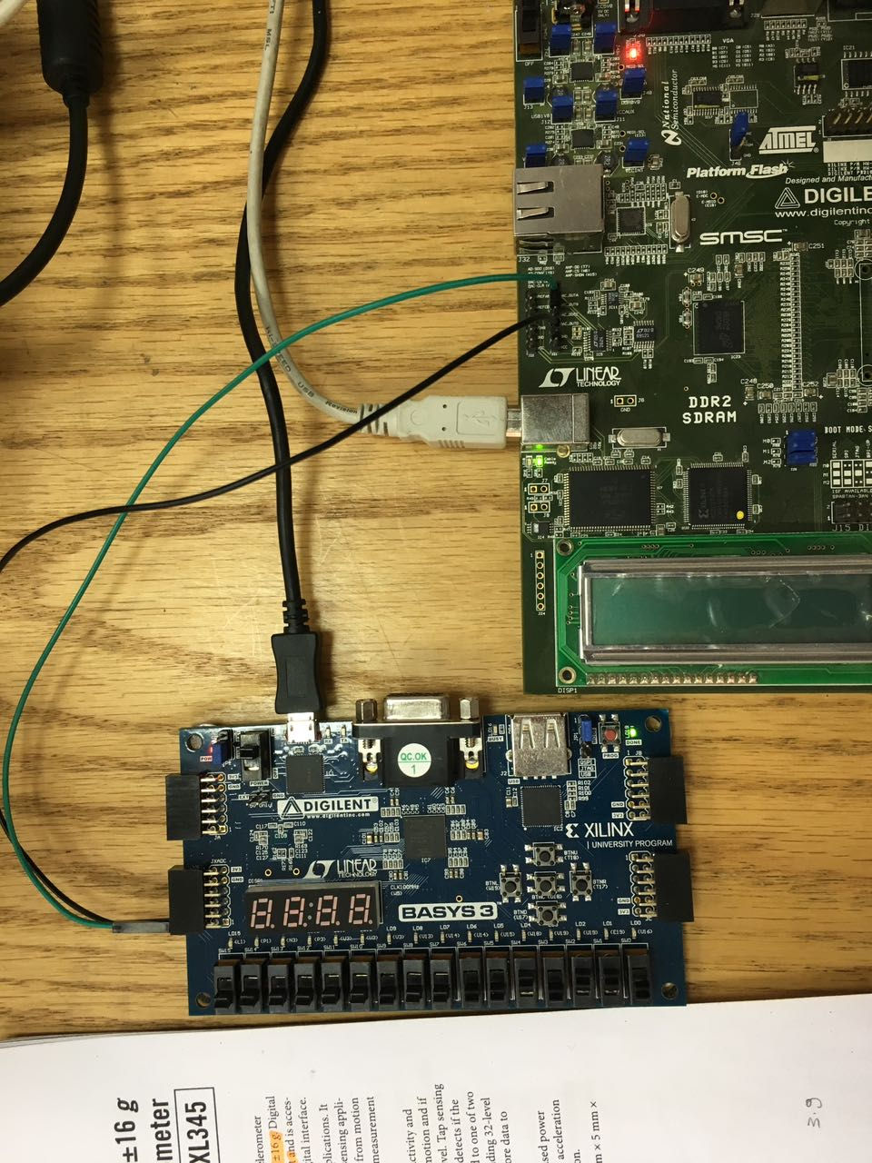
The ila shows the acquired data from the XADC.

Comments