
Tutorial 1 : Controlling LED
- Mar 6, 2018
- 4 min read
Target Board : Zedboard
Introduction
During this tutorial we are going to control the LEDs of the Zedboard to generate different patterns, the LEDs are connected to the PL (Programmable Logic) side of the Zynq SOC, however we can control it using the PS(Processing System) side through GPIO IP.
Step1: Create new project using Vivado IDE
1- Launch Vivado IDE and select create new project.
2- Enter Zedboard_tutorial1 in the project name field and choose a project directory location.

3- Select RTL Project option in the Project Type form, and click Next.
4- Select VHDL as the Target language and Simulator language in the Add Sources form.
5- We are not going to add files, IPs or constraints so click next.
6- In the Default Part form, using the Boards option choose Zedboard Zynq Evaluation and development Kit and click Next then Finish.

Step2: Create Block design
To control the LEDs from the PS, we need to create a block design and add a Zynq SOC block in it, then add AXI GPIO IP core which will be used by the Zynq SOC to control the LEDs
1- In the Flow Navigator click expand the IP Integrator and click create block design, create Design window will pop up, keep the same name design_1 and click ok.

2- After the Diagram page opens, click on the Add IP icon from the left panel of the Diagram page to add IP blocks. Also you can right click on any empty space in the Diagram page and choose Add IP

3- In the search bar type Zynq , and choose the first option, this will add a ZYNQ processing system IP( the ARM cortex A9 processor).

4- Click on the run block automation option, so that the Vivado configures the Zynq IP according to the default settings of the selected board during the create project step (The Zed board). This is called the design assistance, and it appears whenever there is possibility that the Vivado helps to continue the design automatically.

5- Again click on the Add IP icon and this time write in the search bar GPIO, and choose the AXI GPIO, the AXI GPIO IP should appear in the Diagram.

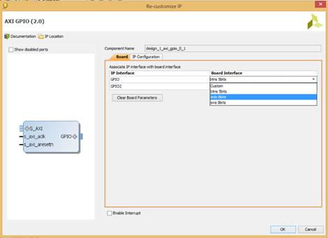
6- Double click on the AXI GPIO IP, under the Board Interface choose leds 8 bit and click ok
7- Now the designer assistance will again show you the option to help by Running Connection Automation, Click on it and choose All Automation then click ok, here you accept the suggestion of connecting the AXI GPIO IP to the ZYNQ, the Vivado will add 2 IPs for you, these IPs are the processor system reset and AXI interconnect.
- The processor system reset is responsible giving reset signals to all peripherals and interconnects in the PL side of the ZYNQ according to reset signal given from the ZYNQ PS.
- The AXI interconnect is responsible for creating an interface between the ZYNQ PS master interface GP port and the AXI GPIO IP.

8- Click on the Regenerate Layout icon to rearrange the blocks in a good organization.

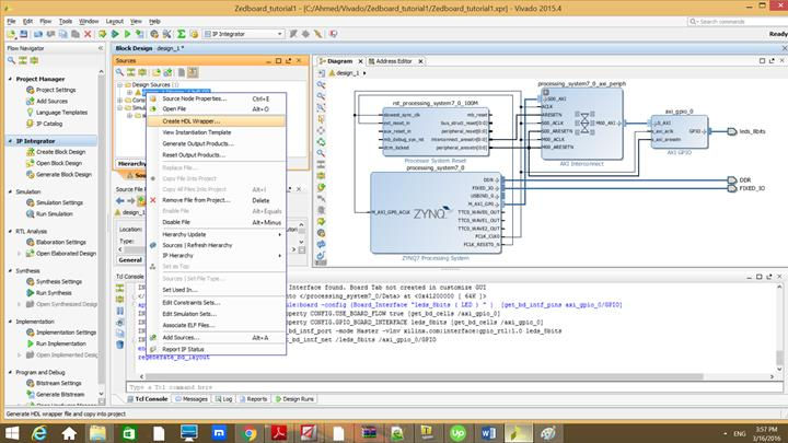
9- In the sources window, right click on the design_1 block design under Design Source folder and choose create HDL wrapper, this options creates a top level VHDL file for the block design which can be used to generate the bitstream file.
10- Choose let Vivado manage wrapper and auto update and click ok

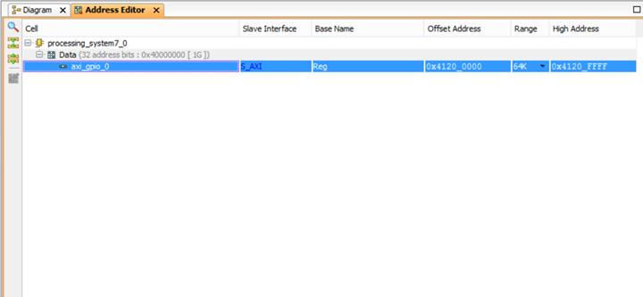
Note: Click on the address editor panel, you shall find the processing system connected to the AXI GPIO IP, with an automatically given offset address. This address will be used by the ZYNQ processor to communicate with the AXI GPIO IP which is connected to the LEDS
11- In the flow navigator, click on generate bitstream or click on flow->generate bitstream. During this step the tool creates a bit file for programming the PL of the ZYNQ.
12- Bit Generation Complete window should pop up, close it then go to File-> Export -> Export Hardware. Check the Include bitstream and click ok. This exports the hardware files generated to the SDK (software development kit).

Step3: writing the software application
During this step we should export the hardware files to the software development kit to create then create a C project for controlling the LEDs from the ZYNQ PS
1- In Vivado go to File-> Launch SDK, the SDK will open and in the Project Explorer window you can see the exported hardware files. In the SDK go to Files-> New-> board support package then click finish, this create a board support package with all necessary functions for driving the hardware you designed in Vivado.

2- Create application project by going to File-> Application Project, in the project name type Project1 and in the board support package choose use existing then click Next and choose Hello World from the available templates then click finish


3- Expand the src folder under the Project1 folder and double click on Helloworld.c and replace it with the following code:

Step4: Programming the Zedboard and running the C Application
1- In the SDK click on the program FPGA icon then click program to program the ZYNQ PL with the bitstream


2- Write click on Project1 in the project explorer then go to Run AS-> 4 Launch on Hardware(GBD). The aplication should run on the board and the LEDs shows the binary values of the counter

Comments