
Radar Display in VHDL
- Mar 6, 2018
- 2 min read
Radar PPI is used to display the range and Azimath of a target as a dot inside range circules, a scanning line usually represents the direction of the Radar antenna. In order to implement a Radar PPI on FPGA a VGA controller must be designed in VHDL, this VGA controller must provide the correct timing and data to display the range circules, the scanning line and the target.

VGA Controller :
The VGA controller sets the RGB values to green on if the VGA scan signals are at the location of the range circules or the scanning line, and it sets the RGB signals to Red when the VGA horizontal sync ad vertical syc are at the estimated location of the target, in this project the target location is fixed, however it can be supplied from external device or another VHDL design code, the following code represents the VGA controller :
the location of the scanning line is generated using Tan function, this is done in VHDL using a Rom initialized with the Tan results of the input address, the memory initialization files is shown below:
the address of this Rom is generated using a free running counter whose reset value is the north pulse of the radar, and the scanning speed is equal to the rotating speed of the antenna a clock divider is utilized to provide the clock for the address generator with the scanning speed
Clock Divider :
Address Generator :
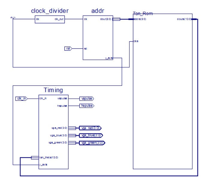
finally the complete design is connected using schematic capture, however it can also be connected in a top level VHDL entity
The final design can be connected directly with ultrasonic distance measurement sensor rotating on a small Motor, please check the video of the project also please provide your questions or suggestions
Comments